
As a part of my work developing Plobot (http://plobot.com/), we were trying to think of ways to improve the robot’s performance on carpet. The trouble is that a degree of wheel slippage is inevitable on carpet, and so encoders cannot be very accurate. Another team member, Maciej, suggested an interesting solution: the sensor from an optical mouse.
So, after doing some reading on the topic, I went around the corner and bought a cheap optical mouse, and took it apart. The inside looked a lot like this:
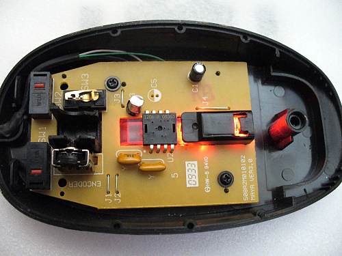
I knew from my reading that the maker of most of these low-cost optical mouse sensors is Pixart, and I saw “KA8” written on the module, so I typed “Pixart KA8” into Google and this datasheet came up: PAW3204DB-TJ3R
Seeing the staggered pin arrangement was the same in that document, I became confident that I had the right datasheet, and I extracted the module from the mouse PCB. I then cobbled together my own circuit based on the schematic in the datasheet, running the module at 3.3v and communicating with it with an Arduino Uno. I added voltage dividers on the two serial lines to level shift.
Unfortunately I saw a lot of garbage coming from the chip, and the serial protocol was not defined in the datasheet. I searched Google some more and came across this more complete datasheet for a related part, which turned out to have the same serial protocol: PAW3204DB
I then realized that the serial synchronization was essential to getting meaningful results from the module. I added code to synchronize every 100 read commands, and was able to read the product ID. As it turned out, I was in fact working with the PAW3204DB, and had been overvolting it the whole time at 3.3v. I was lucky that it held up. I added a voltage divider and a large capacitor on the power supply to get a stable 2.7v, with the optical sensor consuming < 10mA. I also made other minor tweaks such as adding the 34k resistor on OSC_RES.
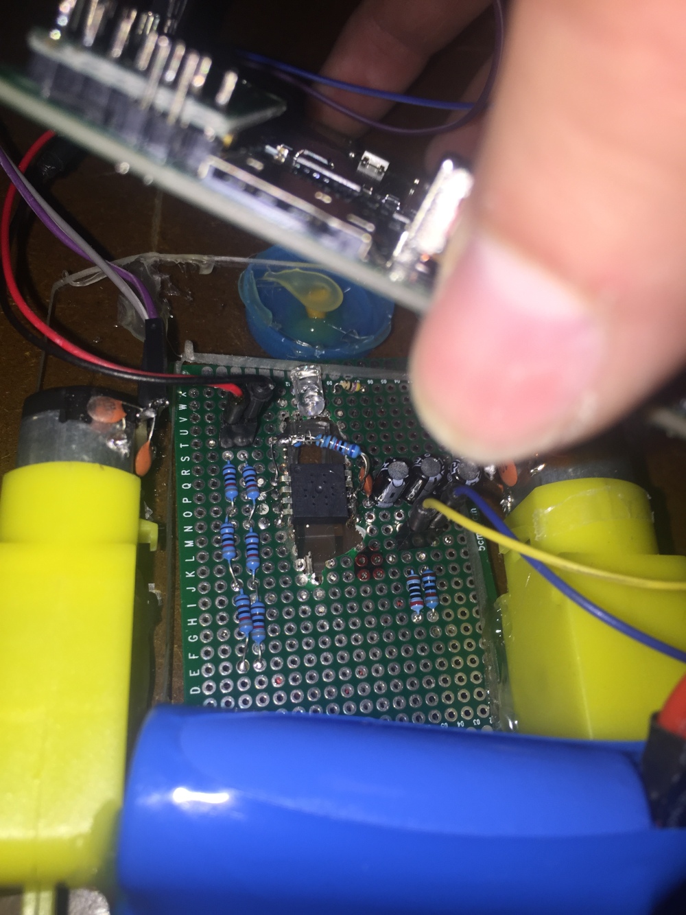
Using the PAW3204DB datasheet, I was able to get tracking data from the optical sensor board, and with the help of another teammate, Rudi, I assembled a rough but adequate robot body to test with. I used the current revision Plobot board I had on hand as a driver.


NOTE the capacitors soldered to the motor leads and case. These EMI suppression capacitors were actually essential to making the robot work! Without them, the optical sensor module would malfunction severely when the motors ran. This issue frustrated me for a few hours.
Finally, after writing a quick and dirty control program using the Atmel microcontroller on the Plobot PCB, I had a working robot built around the optical sensor. No encoders or motor feedback sensors of any kind!
And it worked for my purpose, allowing the robot to tolerate a great deal of wheel slip, almost “skating” on the carpet:
The results with this sensor were not accurate enough to be a full solution for moving on the rug on its own. However, it could work well to complement encoders to detect slip, and I will be experimenting with higher quality sensors as well.
The control program works on the principle that when robot rotates, the optical sensor senses horizontal (X) movement, since its horizontal axis is always tangent to the circle. When the robot moves forward/backward, it senses vertical (Y) movement. So, when going straight, motor power is balanced to minimize X movement. While turning, it is balanced to minimize Y movement. Likewise, when going straight, a certain total Y offset is counted to determine the length moved, and when turning, a certain total X movement is counted.

Very thank you for great information about KA8 (PAW3204DB-TJ3R) sensor.
In fact, I get a KA8 from my mouse and want to use it with arduino mega (or MSP430),
but I’m just a newbie. I read PAW3204DB’s read opeartion and write operation very many times, however, I couldn’t
write right code to read Product ID.
Could you send me a simple code to read Product ID with arduino?
Thank you for reading this reply.
LikeLike
Here is my very messy test code. Hope it helps!
const int pin_d = 30;
const int pin_sc = 29;
void setup() {
pinMode(pin_sc, OUTPUT);
pinMode(pin_d, OUTPUT);
pinMode(motor_l_fwd, OUTPUT);
Serial.begin(9600);
}
void output_bit(int s, boolean release_clk = false)
{
digitalWrite(pin_d, s ? HIGH : LOW);
// delayMicroseconds(5);
digitalWrite(pin_sc, HIGH);
// delayMicroseconds(5);
if(release_clk)
pinMode(pin_d, INPUT);
// delayMicroseconds(1);
digitalWrite(pin_sc, LOW);
// delayMicroseconds(10);
}
int input_bit()
{
digitalWrite(pin_sc, HIGH);
// delayMicroseconds(5);
int ret = (digitalRead(pin_d) == HIGH) ? 1 : 0;
// delayMicroseconds(5);
digitalWrite(pin_sc, LOW);
// delayMicroseconds(10);
return ret;
}
int8_t read_val(int addr) {
pinMode(pin_d, OUTPUT);
output_bit(0);
for(int i=6;i>=1;--i)
output_bit(addr & (1<=0;--i)
val |= (input_bit() <=0;--i)
output_bit(addr & (1<=0;--i)
output_bit(val & (1<<i));
}
const int counts_per_inch_table[8] = {
400,
500,
600,
800,
1000,
1200,
1600,
1,
};
void loop() {
static int sync = 0;
if((sync++) % 100 == 0){
// Synchronize
pinMode(pin_d, OUTPUT);
digitalWrite(pin_sc, LOW);
delayMicroseconds(10);
digitalWrite(pin_sc, HIGH);
delay(4);
pinMode(pin_d, INPUT);
delayMicroseconds(3);
digitalWrite(pin_sc, LOW);
delayMicroseconds(3);
write_val(0x0D, 40);
}
// Read
static boolean overflow_status = false;
static int xtot = 0, ytot = 0;
static long quality_num = 0;
static long quality_denum = 0;
static long cpi_num = 0;
static long cpi_denum = 0;
int8_t st_val = read_val(0x02);
if(st_val & 0x07) {
int8_t x_val = read_val(0x03);
int8_t y_val = read_val(0x04);
xtot += x_val;
ytot += y_val;
const int8_t vr = read_val(0x07);
uint8_t image_quality = *((uint8_t const*)(&vr));
quality_num += image_quality;
quality_denum++;
if(st_val & (1<<3) || st_val & (1< 100) {
// int8_t image_quality = read_val(0x07);
Serial.print("Offset: (");
Serial.print(xtot);
Serial.print(", ");
Serial.print(ytot);
Serial.print(") cpi ");
Serial.print(cpi_num / cpi_denum);
cpi_num = 0;
cpi_denum = 0;
Serial.print(" q ");
Serial.print(quality_num / quality_denum);
quality_num = 0;
quality_denum = 0;
if(overflow_status)
Serial.print(" !! Overflow!");
Serial.println();
overflow_status = false;
xtot = 0;
ytot = 0;
print_millis = millis();
}
}
LikeLike
Thank you! It’s very helpful for me!
I sincerely thank you!
The code you commented has many errors in arudino studio, however, I could catch the important things,
for example, how to make clock-like data, ….and so on.
Finally I corrected the code, and get pretty good value.. (although i have to modify the code more)
Thank you !
Have a nice day
LikeLike
Hi SoonYoung,
Can you please post your code somewhere?
Thank you.
LikeLike
Did you have the schematics?
LikeLike